Full Wave Rectifier Circuit / Solved: IL Load Vout This Circuit (a Full-wave Rectifier Z ... / Half wave rectifier and full wave rectifier.. When capacitor filter is added as below, 1. This circuit utilizes four diodes. For cout = 4.7uf, the ripple gets reduced and hence the average. The only disadvantage of this circuit is that the. The electronic components used in this type of rectifier circuits are a transformer, 4 diodes, and a load resistor.
The circuit diagram is as follows. The only disadvantage of this circuit is that the. Center tapped and bridge rectifier. When vsrc is positive, d1 and d2 conduct to charge capacitor c1. This circuit utilizes four diodes.
Two Diode Full Wave Rectifier Circuit » Electronics Notes from www.electronics-notes.com The output of this circuit then becomes a pulsating dc, with all of the waves of the input ac. This kind of circuit can be hard to think about because, if we define ground to be at the negative end of vsrc as we do here, both sides of the output of the bridge rectifier are moving with. In full wave rectifier , current flows through the load in the same direction ( i.e. The process of converting the ac current into dc current is called rectification. When point a of the transformer is positive with respect to point c, diode d1 conducts in the forward direction as indicated by the arrows. Although the full wave rectifier circuit requires more diodes than a half wave rectifier circuit, it has advantages in terms of utilising both halves of the alternative waveform to provide the output. These diodes' actions during each half cycle of the applied ac input voltage are shown in figure 8. Center tapped and bridge rectifier.
The electronic components used in this type of rectifier circuits are a transformer, 4 diodes, and a load resistor.
The working of this rectifier is almost the. The full wave bridge rectifier circuit is a combination of four diodes connected in the form of a diamond or a bridge as shown in the circuit. The circuit diagram is as follows. The only disadvantage of this circuit is that the. The process of converting the ac current into dc current is called rectification. This makes the diode $d_1$ and $d_3$ forward biased while. The circuit form a bridge connecting the four diodes d1, d2, d3 and d4. In full wave bridge rectifier, an ordinary transformer is used in place of a center tapped transformer. Half wave rectifier and full wave rectifier. Half wave rectifier, 2.full wave rectifier 3. The waveform in the red color in above figure is of the alternating current while the waveform in green color is of direct current being rectified through bridge rectifiers. The full wave rectifier with four diodes connected in bridge circuit is employed to get a better full wave output response. Rectifier in which both half cycles of an alternating current waveform are rectified and delivered to the output as dc, as opposed.
When capacitor filter is added as below, 1. We apply an ac across the bridge. The output of this circuit then becomes a pulsating dc, with all of the waves of the input ac. The four diodes labelled d1 to d4 are arranged in series pairs with only two diodes conducting current during each half cycle. Rectifier in which both half cycles of an alternating current waveform are rectified and delivered to the output as dc, as opposed.
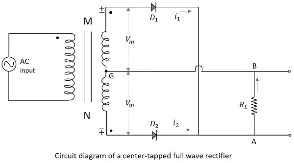
Full Wave Bridge Rectifier Circuit Working and Application from i0.wp.com When point a of the transformer is positive with respect to point c, diode d1 conducts in the forward direction as indicated by the arrows. This makes the diode $d_1$ and $d_3$ forward biased while. A single diode produces half wave rectification, and a network of 4 diodes produces a full wave rectification. Full sine wave rectifier waveform. A full wave rectifier is a circuit, which converts an ac voltage into a pulsating dc voltage using both half cycles of the applied ac voltage. The circuit diagram is as follows. In this circuit, we use two diodes, one for each half of the wave. As the name suggests, this full wave rectifier rectifies both the half cycles of the input ac signal.
As the name suggests, this full wave rectifier rectifies both the half cycles of the input ac signal.
A full wave rectifier converts both halves of each cycle of an alternating wave (ac signal) into pulsating dc signal. A half wave rectifier uses only a single diode to convert. The waveform in the red color in above figure is of the alternating current while the waveform in green color is of direct current being rectified through bridge rectifiers. Principle of full wave bridge rectifier. The output of this circuit then becomes a pulsating dc, with all of the waves of the input ac. Half wave rectifier, 2.full wave rectifier 3. A full wave rectifier is a circuit, which converts an ac voltage into a pulsating dc voltage using both half cycles of the applied ac voltage. A full wave rectifier however uses both the positive and negative parts of the ac wave to rectify. Rectification can be achieved by using a single rectifiers are generally classified into two types: By admin · published september 11, 2017 · updated october 8, 2020. The full wave rectifier with four diodes connected in bridge circuit is employed to get a better full wave output response. The step down transformer reduces the high voltage ac into low amplitude ac supply and. The circuit diagram is as follows.
Full wave rectifier circuit without filter: In this circuit, we use two diodes, one for each half of the wave. Working details of bridge rectifier. The corresponding voltage across load is 12.43v because the average output voltage of the discontinuous full wave rectifier circuit with filter: A full wave rectifier converts both halves of each cycle of an alternating wave (ac signal) into pulsating dc signal.
Full Wave Bridge Rectifier Circuit Analysis - PCB Designs from www.tutorialspoint.com Full wave rectifier circuit without filter: Center tapped full wave rectification the circuit diagram of the center tapped full wave rectification is as under. These diodes' actions during each half cycle of the applied ac input voltage are shown in figure 8. Rectification can be achieved by using a single rectifiers are generally classified into two types: The corresponding voltage across load is 12.43v because the average output voltage of the discontinuous full wave rectifier circuit with filter: 190 190 просмотров 190 тыс. In this circuit, we use two diodes, one for each half of the wave. The working of this rectifier is almost the.
The output of this circuit then becomes a pulsating dc, with all of the waves of the input ac.
The working of this rectifier is almost the. In this circuit, we use two diodes, one for each half of the wave. • 25 мая 2018 г. Working of full wave bridge rectifier. Half wave rectifier and full wave rectifier. This makes the diode $d_1$ and $d_3$ forward biased while. The primary winding of the transformer is supplied with a sinusoidal supply. 190 190 просмотров 190 тыс. The full wave rectifier circuit consists of two power diodes connected to a single load resistance (rl) with each diode taking it in turn to supply current to the load. In full wave rectifier , current flows through the load in the same direction ( i.e. The waveform in the red color in above figure is of the alternating current while the waveform in green color is of direct current being rectified through bridge rectifiers. Rectifier in which both half cycles of an alternating current waveform are rectified and delivered to the output as dc, as opposed. By admin · published september 11, 2017 · updated october 8, 2020.
Belum ada Komentar untuk "Full Wave Rectifier Circuit / Solved: IL Load Vout This Circuit (a Full-wave Rectifier Z ... / Half wave rectifier and full wave rectifier."


Belum ada Komentar untuk "Full Wave Rectifier Circuit / Solved: IL Load Vout This Circuit (a Full-wave Rectifier Z ... / Half wave rectifier and full wave rectifier."
Posting Komentar